Welcome to Chapter 1: Basic Concept
This lab follows the syllabus in order, 1.1 → 1.8. Open one subtopic at a time. Each subtopic has the same four stages. Finish all four, then press Mark complete.
0 of 8 subtopics complete
Course alignment
CO1 (C3, C4) Bloom's Taxonomy: C3 Apply, C4 Analyse PO1: Engineering Knowledge
Attribute the basic concepts of electrical quantities by using basic circuit laws (Ohm's law and Kirchhoff's law) and simplification of resistive circuits.
| Week | Subtopic | Title |
|---|---|---|
| W1 | 1.1 | Introduction of Circuit Analysis |
| 1.2 | Electrical Quantities | |
| W2 | 1.3 | Circuit Elements |
| 1.4 | Ohm's Law and Kirchhoff's Law | |
| W3 | 1.5 | Nodes, Branches and Loops |
| 1.6 | Resistive Circuits | |
| W4 | 1.7 | Voltage Division and Current Division |
| 1.8 | Delta–Wye Transformation |
Main reference: C. Alexander and M. Sadiku, Fundamentals of Electric Circuits, 6th ed., McGraw-Hill, 2016. Further reading: J. Nilsson and S. Riedel, Electric Circuits, 10th ed., Prentice Hall, 2014.
How each subtopic works
Tip: if you get a quiz question wrong, go back to Learn or Simulate, then try again.
1.1 Introduction of Circuit Analysis
AWhy circuit theory?
Electrical engineering studies, designs and applies equipment, devices and systems that use electricity, electronics and electromagnetism.
Electric circuit theory and electromagnetic theory are the two fundamental theories of electrical engineering. Power, control, machines, electronics, communications and instrumentation are all built on circuit theory.
BWhat do electrical engineers do?
- Design new ways to use electrical power
- Perform calculations for construction, installation and manufacturing specifications
- Direct manufacturing, installation and testing so products meet codes
- Investigate complaints, evaluate problems and recommend solutions
- Design, develop and test equipment such as motors, radar, generators and communication systems
CWhat is an electric circuit?
An electric circuit is an interconnection of electrical elements linked together in a closed path so that an electric current can flow continuously.
Left: closed circuit (switch ON), current flows and the lamp lights. Right: open circuit (switch OFF), the path is broken, no current.
| Element | What it does |
|---|---|
| Voltage source | The "battery" of the circuit, provides the energy that pushes current around |
| Resistor | Opposes (limits) the flow of current |
| Capacitor | Stores and releases energy in an electric field, like a small rechargeable battery |
| Inductor | Resists changes in current by storing energy in a magnetic field |
| Conductor (wire) | Connects all the components so current can flow |
| Switch | Opens or closes the path |
DFrom physical layout to circuit diagram
A car headlight system has a battery, a switch, wires and two headlamps. In a circuit diagram we replace each part with a standard symbol: the battery becomes a voltage source, and each headlamp becomes a resistor. The diagram is easier to analyse than the physical layout.

Figure (a) from the Chapter 1 lecture notes, Part 1, slide 10.
Open or closed? Try the switch
What to notice
- Closed path → current flows → the lamp converts electrical energy into light and heat.
- Open path → no current, even though the battery still has voltage across it.
- Conventional current flows out of the + terminal, around the circuit, into the − terminal.
- Electrons actually move the other way (− to +). In this course we always use conventional current.
1.2 Electrical Quantities
The big picture
ASI units
The International System of Units (SI) lets engineers everywhere communicate results in the same way.
| Quantity | Symbol | Unit | Abbr. |
|---|---|---|---|
| Charge | Q, q | coulomb | C |
| Current | I, i | ampere | A |
| Voltage | V, v, E | volt | V |
| Power | P | watt | W |
| Energy | W | joule | J |
| Resistance | R | ohm | Ω |
| Conductance | G | siemens | S |
| Capacitance | C | farad | F |
| Inductance | L | henry | H |
| Frequency | f | hertz | Hz |
| Time | t | second | s |
BSI prefixes
| Multiplier | Prefix | Symbol | Example |
|---|---|---|---|
| 1012 | tera | T | 2 TB |
| 109 | giga | G | 12 GHz |
| 106 | mega | M | 25 MΩ |
| 103 | kilo | k | 13.2 kV |
| 10−2 | centi | c | 30.2 cm |
| 10−3 | milli | m | 5 mH |
| 10−6 | micro | µ | 6.5 µW |
| 10−9 | nano | n | 3 ns |
| 10−12 | pico | p | 9 pF |
15 mA + 8000 µA = 15 mA + 8 mA = 23 mA.
CCharge
Electric charge is the property of subatomic particles that makes them feel a force in an electric or magnetic field. It can be positive or negative, and is measured in coulombs (C).
| Charge of one electron | e = −1.602 × 10⁻¹⁹ C |
| Electrons in 1 coulomb | 1 C = 6.24 × 10¹⁸ electrons |
Static shock from a doorknob: charge built up on your body discharges into the metal, which is at earth potential. Fuel trucks and buildings are grounded so charge flows safely to earth.
DCurrent
Current is the time rate of flow of charge, measured in amperes (A). 1 A = 1 C of charge passing a point in 1 s.
rearranged to find charge
Conventional current flows from the + terminal to the − terminal of the source.
| DC (direct current) | AC (alternating current) | |
|---|---|---|
| Behaviour | Constant with time, one direction | Varies sinusoidally, reverses direction |
| Sources | Batteries, fuel cells, solar cells | Power plants, wall socket |
DC: same value at all times, always one direction
AC: value changes and direction reverses (+ then −)
EVoltage
Voltage (potential difference) is the energy needed to move a unit charge through an element. 1 V = 1 J/C.
- V
- voltage (V)
- W
- work / energy (J)
- Q
- charge (C)
Also called potential difference, e.m.f., supply voltage or voltage source (symbol Vs or E). When current flows through an element, a voltage drop appears across its terminals.
FPower
Power is the time rate of expending or absorbing energy, measured in watts (W).
1 hp = 746 W. A 100 W bulb gives more light than a 60 W bulb.
GPassive sign convention
- Current enters the + terminal → p = +vi → power absorbed (element is a load).
- Current enters the − terminal → p = −vi → power supplied (element is a source).
- Conservation of energy: ΣP = 0, so power supplied = power absorbed.
Slide Example 2: check ΣP = 0.
HEnergy
Energy is the capacity to do work, measured in joules (J).
- t in seconds → W in joules (watt-seconds)
- t in hours → W in watt-hours (Wh) or kWh. The utility company bills in kWh.
IElectricity bill (tiered rate)
Example 5: 700 kWh in January. Base charge RM 12.00; first 100 kWh at 16 sen; next 200 kWh at 10 sen; above 300 kWh at 6 sen.
▶ Try the Energy & Bill Calculator in Simulate.
🔁 Prefix converter
Type a value, choose its prefix, then choose the prefix you want.
⚡ Passive sign convention explorer
🏠 Energy & Bill Calculator
Edit the appliance list (power in W, time in hours). Default values are from Exercise 11.
Tiered bill (Example 5 schedule). Change the monthly usage.
1.3 Circuit Elements
APassive and active elements
| Passive element | Active element | |
|---|---|---|
| Energy | Cannot generate energy; absorbs or stores it | Capable of generating (supplying) energy |
| Examples | Resistor, capacitor, inductor | Voltage source, current source, generator, battery |
BIndependent sources (circle symbol)
An independent source provides a specified voltage or current that does not depend on any other circuit variable.
Left: independent voltage source. Right: independent current source (arrow shows current direction).
CDependent (controlled) sources (diamond symbol)
A dependent source provides a voltage or current that is controlled by another voltage or current somewhere in the circuit. There are four types:
| Type | Output | Controlled by | Form |
|---|---|---|---|
| VCVS | voltage | a voltage | v = μ vx |
| CCVS | voltage | a current | v = r ix |
| VCCS | current | a voltage | i = g vx |
| CCCS | current | a current | i = β ix |
DResistance and resistivity
Resistance is the ability of a material to resist the flow of current. For a uniform conductor of length l and cross-sectional area A:
- ρ
- resistivity of the material (Ω·m)
- l
- length (m)
- A
- cross-sectional area (m²)
| Material | ρ (Ω·m) | Use |
|---|---|---|
| Silver | 1.64 × 10⁻⁸ | Conductor |
| Copper | 1.72 × 10⁻⁸ | Conductor |
| Aluminium | 2.8 × 10⁻⁸ | Conductor |
| Gold | 2.45 × 10⁻⁸ | Conductor |
| Carbon | 4 × 10⁻⁵ | Semiconductor |
| Germanium | 47 × 10−2 | Semiconductor |
| Silicon | 6.4 × 10² | Semiconductor |
| Paper | 1010 | Insulator |
| Mica | 5 × 10¹¹ | Insulator |
| Glass | 1012 | Insulator |
Table after Alexander & Sadiku, Table 2.1.
EResistors
A resistor is a passive element used to limit current or divide voltage. Unit: ohm (Ω). 1 Ω exists when 1 V across it drives 1 A through it.
- Fixed resistor: value is constant, identified by its colour code. Bigger body = higher power rating (2 W, 1 W, ½ W, ¼ W, ⅛ W).
- Variable resistor (potentiometer): three terminals with a sliding wiper. Using one end and the wiper gives a rheostat.
Conductance
Conductance measures how easily current flows. In parallel circuits, conductances simply add.
FResistor colour code
4-band: digit · digit · multiplier · tolerance
5-band: digit · digit · digit · multiplier · tolerance
GMeasuring with a multimeter
Resistance (ohmmeter)
Turn OFF / disconnect the supply. Connect the meter across the resistor only.
Current (ammeter)
Break the circuit and put the ammeter in series so the same current flows through it.
Voltage (voltmeter)
Put the voltmeter in parallel across the component. Reversed leads give a negative reading.
▶ Try the Meter Placement Lab to see what happens when a meter is connected wrongly.
🎨 Resistor colour code decoder
🔌 Meter Placement Lab
Your task: connect a multimeter to measure the resistor R correctly. Choose the meter, how to connect it, and whether the supply is ON or OFF. The meter screen shows what you would really see in the lab.
1.4 Ohm's Law and Kirchhoff's Law
The big picture
AOhm's Law
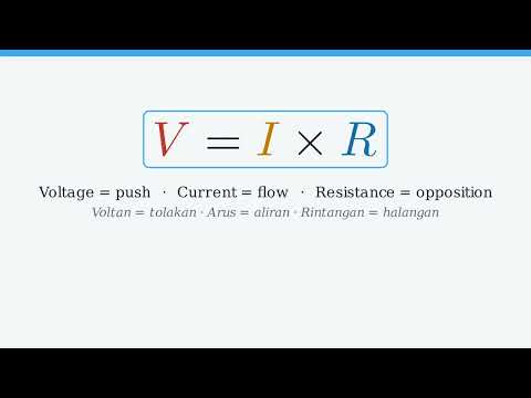
"The voltage V across a resistor is directly proportional to the current I flowing through it."
Memory aid: cover the one you want.
With R fixed, V and I are linearly proportional (straight-line V–I graph). With V fixed, I and R are inversely related.
BOhm's Law with the power equation
▶Video: Ohm's Law
Watch this after reading Ohm's Law above, then try the Ohm's Law explorer in Simulate.
Video not playing? Open it on YouTube.
COpen circuit and short circuit
| Resistance | Voltage across | Current through | |
|---|---|---|---|
| Short circuit | R = 0 | v = 0 | any value (set by the rest of the circuit) |
| Open circuit | R = ∞ | any value | i = 0 |
DKirchhoff's Current Law (KCL)
The sum of currents entering a node equals the sum of currents leaving it. Equivalently, the algebraic sum of currents at a node is zero.
or, taking currents entering as + and leaving as −
KCL comes from conservation of charge: charge cannot pile up at a node.
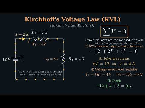
EKirchhoff's Voltage Law (KVL)
The algebraic sum of all voltages around a closed loop is zero: sum of rises = sum of drops.
or, going around the loop with signs
▶Video: Kirchhoff's Laws (KCL and KVL)
Watch this after reading KCL and KVL above, then try the KCL and KVL explorers in Simulate.
Video not playing? Open it on YouTube.
FUsing KVL and KCL together (slide KVL & KCL Example 1)
📈 Ohm's Law explorer
🔀 KCL node explorer
Set four known currents (positive = arrow as drawn, negative = opposite). KCL finds the unknown Ix.
🔁 KVL loop explorer
🧩 Two-loop solver (KVL + KCL)
1.5 Nodes, Branches and Loops
ADefinitions
- Element
- a component or a source
- Branch
- a path that represents a single element
- Node
- a point of connection between two or more branches (a whole wire counts as one node)
- Essential node
- a node where three or more branches join
- Loop
- any closed path in a circuit
- Mesh
- a loop that does not enclose any other loop
BSlide Example 1
- 4 elements → 4 branches (10 V, 5 Ω, 6 Ω, 2 A)
- 3 nodes (coloured), 2 of them essential
- 3 loops, 2 meshes → check: l = 4 − 3 + 1 = 2 ✓
CSeries connection
Two elements are in series if they share a single node and no other element connects to that node. Series elements carry the same current.
DParallel connection
Elements are in parallel if they are connected to the same two nodes. Parallel elements have the same voltage.
ESlide Example 5
- 5 elements → 5 branches: 10 V, 1 Ω, 2 Ω, 5 Ω, 4 Ω
- 3 nodes; 3 meshes (5 − 3 + 1 = 3); 6 loops in total
- Parallel: 1 Ω ∥ 2 Ω, and 10 V ∥ 4 Ω
- The 5 Ω is neither in series nor in parallel with a single element.
▶ Try the Circuit Explorer: turn on the node, branch and mesh overlays for each circuit.
🔍 Circuit Explorer
1.6 Resistive Circuits
ASeries circuit
- The same current flows everywhere: I = Vs/Req
- Each drop: Vk = I Rk; larger R → larger drop
- KVL: Vs = V1 + V2 + V3 + V4
- Polarity of the drop: current enters the resistor at +
BParallel circuit
- The same voltage across every branch: Vs = V1 = V2 = V3
- Branch current: Ik = Vs/Rk
- KCL: Is = I1 + I2 + I3
- Req is always smaller than the smallest resistor.
CVoltage sources in series
Sources in series add algebraically. Aiding sources add; an opposing source subtracts.
Series vs parallel in practice
| Series | Parallel |
|---|---|
| One element fails → the whole string stops working | One branch fails → the other branches still work |
| Req is large → less current | Every branch gets the full supply voltage |
DSeries-parallel: the reduction method
- Start from the side furthest from the source (solve from right to left).
- Combine resistors that are clearly in series or clearly in parallel.
- Redraw the circuit after each step. Label the nodes to see the connections.
- Repeat until one Req is left.
▶ Step through this in the Reduction Stepper.
ELaboratory measurement
Req (ohmmeter)
Remove the supply, then connect the ohmmeter across the two ends of the whole network. It reads Req = R1 + R2.
Current (ammeter)
Break the circuit and connect the ammeter in series, so the same current flows through it.
Voltage (voltmeter)
Connect the voltmeter in parallel across the resistor. In a parallel circuit, every voltmeter reads the same value.
🔧 Series / parallel builder
🪜 Reduction stepper
1.7 Principles of Voltage Division and Current Division
AVoltage Divider Rule (VDR), series
In series, the larger the resistance, the larger its share of the voltage. VDR finds the voltage without first finding the current.
General: vk = RkRT × v for any number of series resistors.
BCurrent Divider Rule (CDR), parallel
In parallel, the total current is shared in inverse proportion to the resistance: the smaller resistor takes more current.
CVDR and CDR in a series-parallel circuit (slide Example 2)
➗ VDR explorer (series)
Resistances in kΩ.
🔱 CDR explorer (parallel)
Resistances in kΩ.
1.8 Delta–Wye Transformation
AWhy do we need it?
In some circuits, like the bridge network, resistors are neither in series nor in parallel. We cannot reduce them with the usual rules.
The fix: replace a three-terminal Δ (delta / pi) group with an equivalent Y (wye / tee) group, or the other way round. After the swap, series and parallel rules work again.
BWye (Y) / Tee (T)
Three resistors meet at one common centre node.
CDelta (Δ) / Pi (π)
Three resistors form a triangle between three nodes.
DΔ → Y
Each Y resistor = product of the two Δ resistors that touch the same terminal ÷ sum of all three Δ resistors.
↳ R1 is at terminal 1. Rb (terminal 1 to 3) and Rc (terminal 1 to 2) are the two Δ resistors that touch terminal 1.
↳ R2 is at terminal 2. Rc (terminal 1 to 2) and Ra (terminal 2 to 3) touch terminal 2.
↳ R3 is at terminal 3. Ra (terminal 2 to 3) and Rb (terminal 1 to 3) touch terminal 3.
EY → Δ
Each Δ resistor = (R1R2 + R2R3 + R3R1) ÷ the Y resistor at the terminal it does NOT touch.
↳ Ra is connected from terminal 2 to terminal 3. It does not touch terminal 1, so divide by R1 (the Y resistor at terminal 1).
↳ Rb is connected from terminal 1 to terminal 3. It does not touch terminal 2, so divide by R2.
↳ Rc is connected from terminal 1 to terminal 2. It does not touch terminal 3, so divide by R3.
GUnderstanding Y ⇄ Δ step by step
Step 1: both networks share the same three terminals
The Y and the Δ connect to the same terminals 1, 2 and 3. They are equivalent when the resistance measured between any two terminals is the same for both.
Step 2: learn the opposite pairs
| Y resistor | Y resistor is connected from | Opposite Δ resistor | Δ resistor is connected from |
|---|---|---|---|
| R1 | terminal 1 to the centre node | Ra | terminal 2 to terminal 3 |
| R2 | terminal 2 to the centre node | Rb | terminal 1 to terminal 3 |
| R3 | terminal 3 to the centre node | Rc | terminal 1 to terminal 2 |
Opposite pair: R1 goes to terminal 1, while Ra is connected from terminal 2 to terminal 3, the side of the triangle facing away from terminal 1 (it does not touch terminal 1).
Each Y resistor sits at one terminal. Multiply the two Δ resistors that touch that terminal, then divide by the sum of all three.
First find N = R1R2 + R2R3 + R3R1. N is the same for all three. Each Δ resistor = N ÷ the Y resistor opposite it (see the table).
Worked example 1: Y → Δ
Worked example 2: Δ → Y
▶ Try your own values in the Δ ⇄ Y converter.
FBalanced case and naming
or
When all three resistors are equal.
🔺 Δ ⇄ Y converter
🌉 Bridge network solver
🏁 Chapter 1 Quiz
15 questions drawn at random from all eight subtopics. Press New quiz for a different set.